Recommended Products
Contact Us
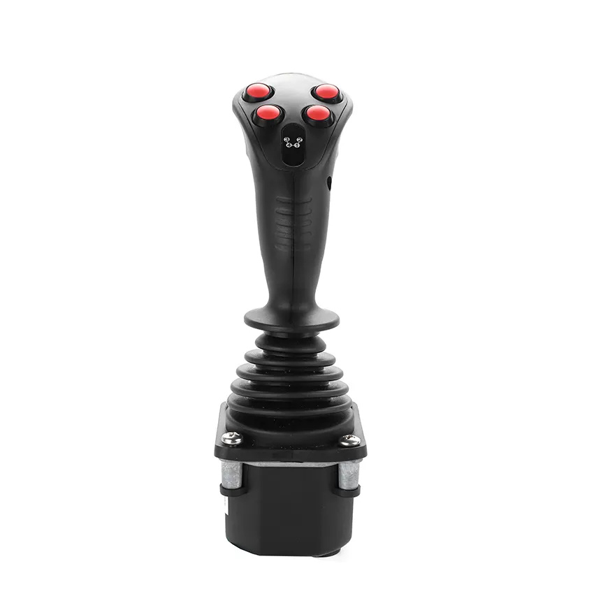
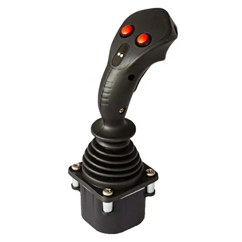
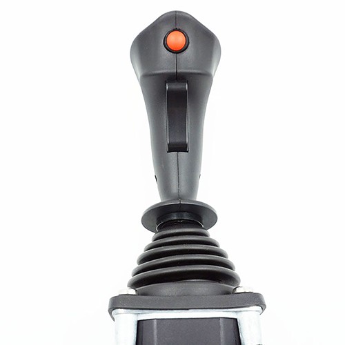
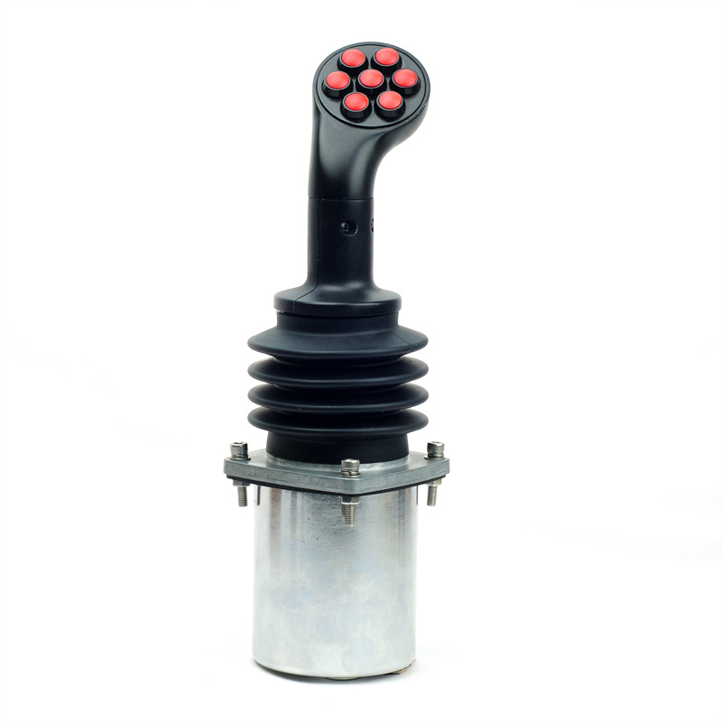
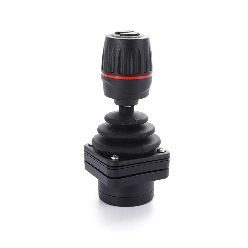
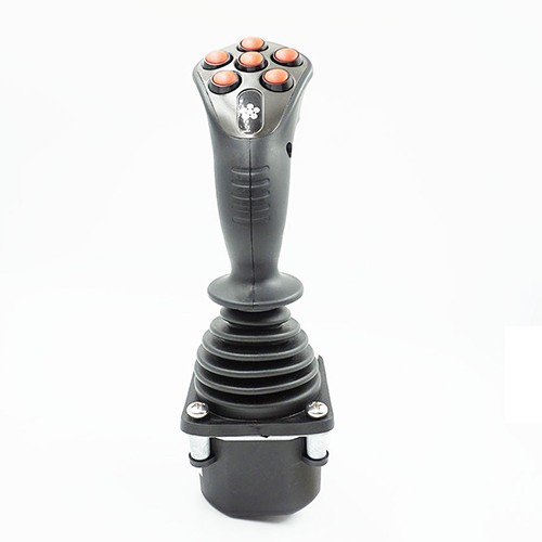
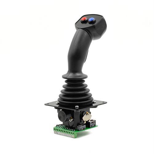
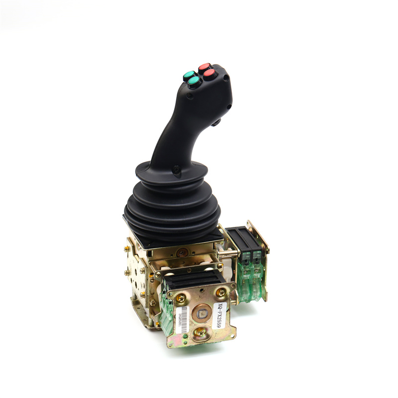
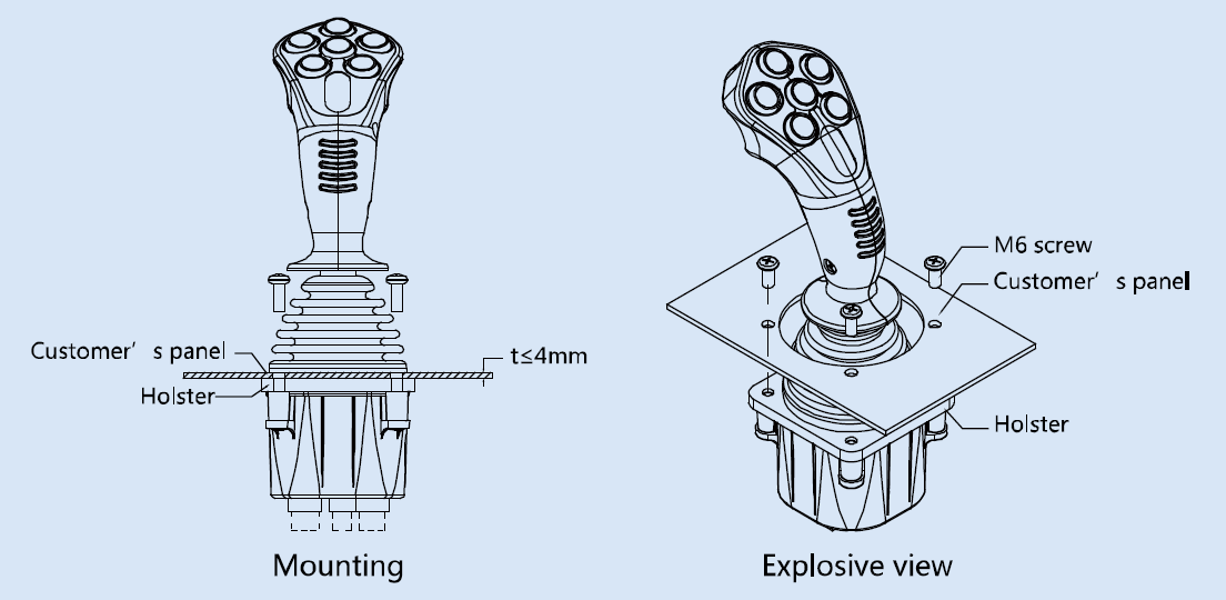
Multi-axis hand operated joystick
Product Features
● Ergonomics design on mobile application
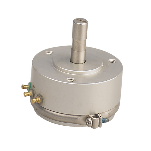
● Uncontact hall effect and long expect-life potentiometer optional
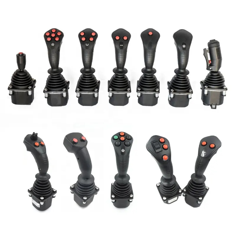
● Various handle, different number and location of button switches optional
● CAN bus output optional
Application
Typical application on Cranes, loaders, Forklifts, excavators, access platform, tractors, harvesters.and so on.
| Travel angle | ±20° |
| Operating type | Spring return |
| Breakout force | 7N |
| Operating force (max) | 16N |
| Maximum allowable force | >300N |
| Expecting life | >2 million cycles (Potentiometer) |
| >5 million cycles (Hall effect) | |
| Weight | 475g (Without handle) |
| Potentiometer | |
| Power supply | < 36Vdc |
| Resistance | 2KΩ,4KΩ,5KΩ,10KΩ |
| Electrical angle | ±18° |
| Center voltage | 48% ~ 52% (power supply) |
| Center tap angle | ±2.5° |
| On-load voltage (max) | 32Vdc |
| Power dissipation | 0.25W (25°) |
| Directional switch | Load capacity: 2mA@30Vdc (Resistance load) |
| Breakout angle:±3° ~5° | |
| Contact resistance: < 200Ω | |
| Hall | |
| Power supply | 5.0+0.5Vdc |
| Supply current | <11mA (Each of hall effect) |
| Maximum allowable overload voltage | 20Vdc |
| Reverse maximum allowable voltage | -10Vdc |
| Output linearity tolerance | <±4V |
| With electronic amplifier | |
| Power supply | 18 ~ 36Vdc (U21 ~ U24) |
| 9~ 36Vdc | |
| Power current consumption | < 20mA |
| Maximum output current | 10mA |
| Can Bus | |
| Power supply | 9 ~ 36Vdc |
| CAN Version | CAN 2.0B |
| Protocol | J1939 |
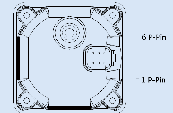
| Connector | 6 p-pin (Deutsch) |
| Microswitch | |
| Load capacity | 4A@30Vdc (Resistance load) |
| Expecting life | 30 million times (Mechanical) |
| 200 thousand times (Electrical) | |
| Insulation resistance | > 100MΩ |
| Breakout angle | ±3°~5° |
| Operating temperature | -30℃~+70℃ |
| Storage temperature | -40℃~+85℃ |
| Protection level | IP65 (Above the flange) |
| Type | SJ60 - □□□ - □□□ - □□□ - □□□ - □□□ - □□□ |
| Code | ① - ② - ③ - ④ - ⑤ - ⑥ - ⑦ |
① Product type
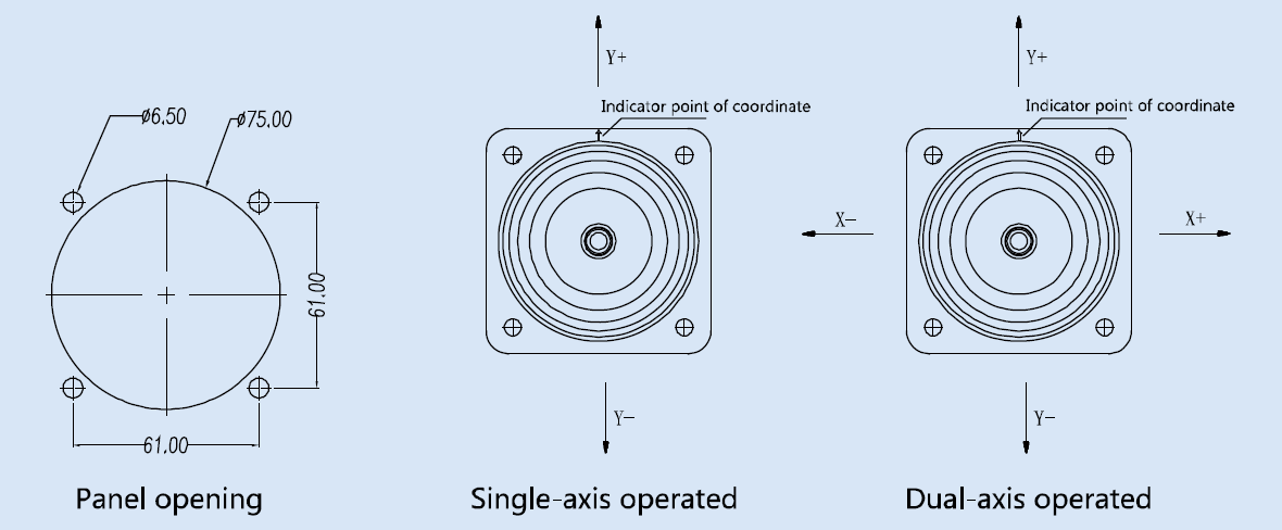
SJ60 series joystick, spring return, installation dimension 61mm*61mm
② Operating type
| 1A | Spring return, single-axis forward and backward directional operated |
| 2AP | Spring return, dual-axis cross directional operated |
| 2AC | Spring return, dual-axis arbitrary directional operated |
③ Selection of spring
| L | Light spring, breakout force4.5N,operating force 9N |
| M | Medium spring, breakout force5N,operating force 11N(standard) |
| H | Heavy spring, breakout force9N,operating force 19N |
④ Output signal
| P021* | Potentiometer,<36Vdc power supply, with 2KΩ center-tapped potentiometer,0%-100%Vdc output |
| P022 | Potentiometer,<36Vdc power supply, with 2KΩ center-tapped potentiometer,10%-90%Vdc output |
| P023* | Potentiometer,<36Vdc power supply, with 2KΩ center-tapped potentiometer,25%-75%Vdc output |
| P051 | Potentiometer,<36Vdc power supply, with 5KΩ center-tapped potentiometer,0%-100%Vdc output |
| P052 | Potentiometer,<36Vdc power supply, with 5KΩ center-tapped potentiometer,10%-90%Vdc output |
| P053 | Potentiometer,<36Vdc power supply, with 5KΩ center-tapped potentiometer,25%-75%Vdc output |
| P101 | Potentiometer,<36Vdc power supply, with 10KΩ center-tapped potentiometer,0%-100%Vdc output |
| P102 | Potentiometer,<36Vdc power supply, with 10KΩ center-tapped potentiometer,10%-90%Vdc output |
| P103 | Potentiometer,<36Vdc power supply, with 10KΩ center-tapped potentiometer,25%-75%Vdc output |
| H51 | Hall effect, each axis of single hall sensor,5Vdc power supply,0.5~2.5~4.5V output voltage |
| H52 | Hall effect, each axis of single hall sensor,5Vdc power supply,0~2.5~5.0V output voltage |
| H53 | Hall effect, each axis of single hall sensor,5Vdc power supply,1.25~2.5~3.75V output voltage |
| H54 | Hall effect, each axis of single hall sensor,5Vdc power supply,1.0~2.5~4.0V output voltage |
| H55 | Hall effect, each axis of single hall sensor,5Vdc power supply,1.15~2.5~3.85V output voltage |
| 2H51 | Hall effect, each axis of redundant hall sensor,5Vdc power supply,0.5~2.5~4.5V output voltage |
| 2H52 | Hall effect, each axis of redundant hall sensor,5Vdc power supply,0~2.5~5.0V output voltage |
| 2H53 | Hall effect, each axis of redundant hall sensor,5Vdc power supply,1.25~2.5~3.75V output voltage |
| 2H54 | Hall effect, each axis of redundant hall sensor,5Vdc power supply,1.0~2.5~4.0V output voltage |
| 2H55 | Hall effect, each axis of redundant hall sensor,5Vdc power supply,1.15~2.5~3.85V output voltage |
| U21 | With electronic amplifier,18-36Vdc power supply,-10V-0V-+10V output voltage |
| U22 | With electronic amplifier,18-36Vdc power supply,+10V-0V-+10V output voltage |
| U23 | With electronic amplifier,18-36Vdc power supply,-5V-0V-+5V output voltage |
| U24 | With electronic amplifier,18-36Vdc power supply,+5V-0V-+5V output voltage |
| I21 | With electronic amplifier,9-36Vdc power supply, 2-wire system 4mA~12mA~20mA output current |
| I22 | With electronic amplifier,9-36Vdc power supply, 2-wire system 20mA~4mA~20mA output current |
| J33 | CAN bus output ,9-36Vdc power supply Can 2.0B output, source address 33 |
| J34 | CAN bus output ,9-36Vdc power supply Can 2.0B output, source address 34 |
| J35 | CAN bus output ,9-36Vdc power supply Can 2.0B output, source address 35 |
| J36 | CAN bus output ,9-36Vdc power supply Can 2.0B output, source address 36 |
| NA | Without analog signal output |
The option with * is custom made
5. Micro switch (not available for CAN bus output)
| MS00 | Without micros witch |
| MS12 | With 4A before and after microswitch (not available for dual-axis cross directional operated) |
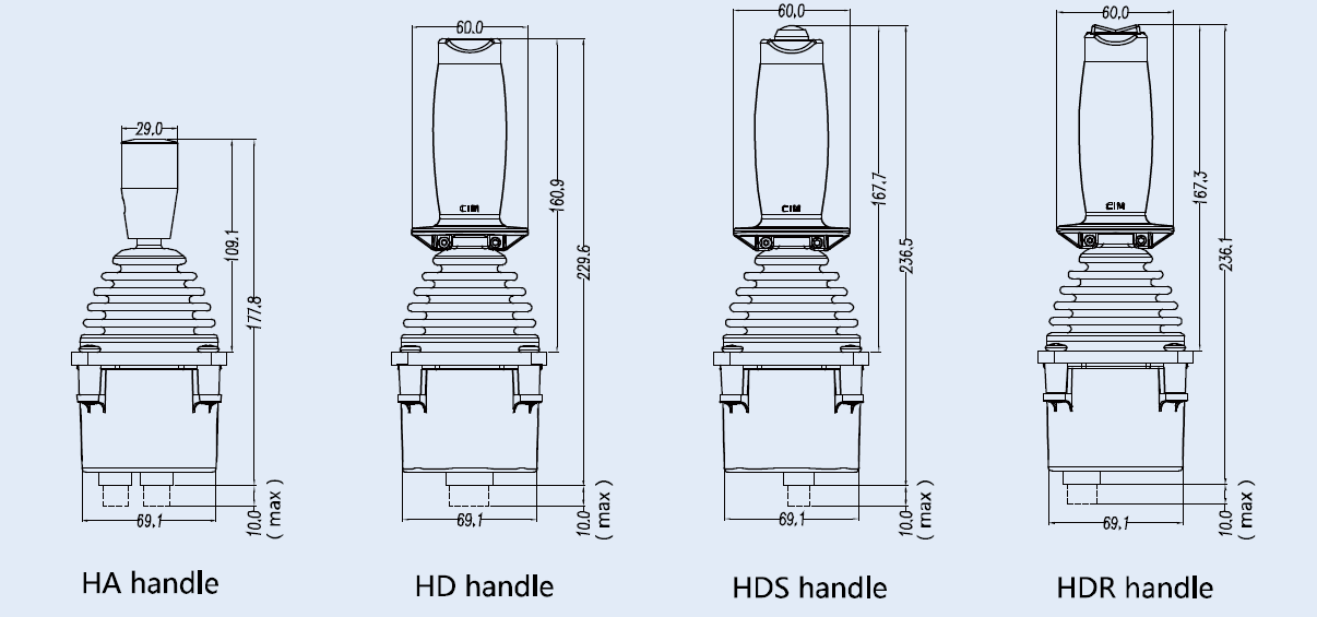
6. Handle
| HA | HA type handle, top without button |
| HAS | HAS type handle, top with button |
| HD | HD type handle, top without button |
| HDS | HDS type handle, top with button |
| HDR | HDR type handle, top with rocker switch |
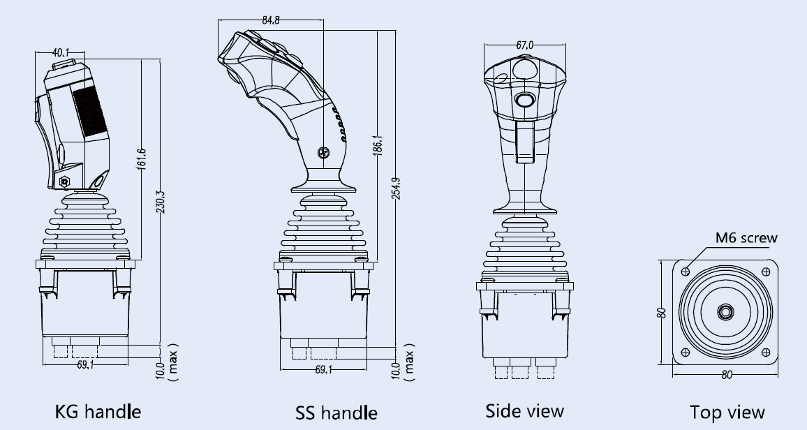
| HGDR | KG type handle, with deadman switch and rocker switch |
| HGDN | KG type handle, with deadman switch, without rocker switch |
| SS | See SS page |
7. Connection
| D | Deutsch connector (only available for CAN bus output) |
| A | AMP connector |
| Pin | CAN |
| 1 | GND |
| 2 | Power supply |
| 3 | Can high |
| 4 | Can low |
| 5 | Can shield |
| 6 | No connection |

AMP connector:
| Connector | Pin | Potentiometer | Hall effect |
| 16 ways connector | 1 | Y-axis forward directional switch | Button switch 4 |
| 2 | N/A | Button switch 3 | |
| 3 | X -axis pot left terminal | Button switch 2 | |
| 4 | X-axis pot wiper | Button switch 1 | |
| 5 | X-axis pot right terminal | Top switch | |
| 6 | X -axis pot center tap | Button switch 5 | |
| 7 | X-axis switch common terminal | Button switch 6 | |
| 8 | X-axis left directional switch | Deadman switch | |
| 9 | Y-axis pot backward teminal | N/A | |
| 10 | Y-axis pot wiper | N/A | |
| 11 | Y-axis pot forward terminal | Common terminal of button switch | |
| 12 | Y-axis pot center tap | Deadman switch | |
| 13 | Y-axis switch common terminal | N/A | |
| 14 | Y-axis backward directional switch | N/A | |
| 15 | X-axis right directional switch | N/A | |
| 16 | N/A | N/A | |
| 12 ways connector | 1 | Button switch 4 | +5V power supply (hall effect sensor 3&4) |
| 2 | Button switch 3 | 0V power supply (hall effect sensor 3&4) ) | |
| 3 | Button switch 2 | +5V power supply (hall effect sensor 1&2) | |
| 4 | Button switch 1 | 0V power supply (hall effect sensor 1&2) | |
| 5 | Top switch | Y-axis output (hall effect sensor 3) | |
| 6 | Button switch 5 | X-axis output (hall effect sensor 2) | |
| 7 | Button switch 6 | X-axis output (hall effect sensor 4) | |
| 8 | Deadman switch | Y-axis output (hall effect sensor 1) | |
| 9 | N/A | N/A | |
| 10 | N/A | N/A | |
| 11 | Button switch common terminal | N/A | |
| 12 | Deadman switch | N/A | |
| 8 ways connector | 1 | Secondary Y-axis pot forward | Forward directional microswitch common terminal |
| 2 | Secondary Y-axis pot center tap | Forward directional microswitch common terminal | |
| 3 | Secondary Y-axis pot wiper | Backward directional microswitch output terminal | |
| 4 | Secondary Y-axis pot backward | Backward directional microswitch common terminal | |
| 5 | Secondary X-axis pot left | Left directional microswitch common terminal | |
| 6 | Secondary X-axis pot wiper | Left directional microswitch output terminal | |
| 7 | Secondary X-axis pot center tap | Right directional microswitch output terminal | |
| 8 | Secondary X-axis pot right | Right directional microswitch common terminal |
The wiring diagram is only applicable to the SS handle, the wiring diagram of other types handles with the goods issue.
HuiRen Electronic is proud to be one of the leader of condustive plastic potentiometer , Industrial joystick.
Copyright©2023 Zhejiang huiren electronics co., ltd
Design By: 057123.com
 浙公网安备 33059102000323号